First, I will give you some basic info about I2C bus, which is used on Panasonic plasmas for communicating to all the board’s EEPROMs. This snip is taken from Wikipedia.
I2C (Inter-Integrated Circuit, referred to as I-squared-C, I-two-C, or IIC) is a multimaster serial single-ended computer bus invented by Philips used for attaching low-speed peripherals to a motherboard, embedded system, cellphone, or other electronic device.
I2C uses only two bidirectional open-drain lines, Serial Data Line (SDA) and Serial Clock (SCL), pulled up with resistors. Typical voltages used are +5 V or +3.3 V although systems with other voltages are permitted.
The I2C reference design has a 7-bit or a 10-bit (depending on the device used) address space.
There’s a lot to know about I2C but for our purposes we just need the basics (you can still read the Wikipedia article or google for more information on this subject).
Arduino UNO, when operated in I2C mode, uses two analog pins A4 (SDA) and A5 (SCL) for I/O and 7-bit addressing scheme when accessing the bus. Panasonic plasmas have only one EEPROM chip on each I2C bus, therefore we will always be addressing the first device on the bus. Since the first four bits are always 1010, adding the address of first device on the bus (000) makes the address to be 1010000 = 0x50 HEX.
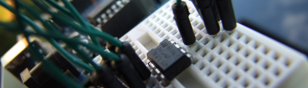
Therefore for our testbed we will connect first three pins to ground making the address 000, pins 5 and 6 to SDA (A4) and SCL (A5) pins on Arduino and pins 7-8 to 5V. Here is a complete schematic.
-

- Arduino testbed schematics
Once you have all the wiring complete, you can load the read EEPROM sketch file eeprom_read.ino into Arduino IDE and compile and upload it to the board. Once successful, you can activate the Serial Monitor from the IDE (under Tools->Serial Monitor or shortcut CTRL+SHIFT+M). You should see the contents of the first ten bytes of the test EEPROM (which would probably be all ones on new chip – 0xFF).
-
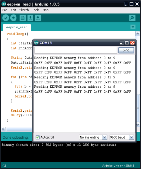
- Serial Monitor reading values from test EEPROM.

As practice, you can edit the start and end addresses in the loop() section, allowing you to read desired bytes from the EEPROM. If you are using EEPROM chip M24C64 it has 64kbit (8,192 Bytes) of addressable space. Therefore you should be able to read bytes 0-8191. If you step over that, the addresses will loop (reading of address 8192 will actually be fetched from byte address 0).
void loop()
  {
    int StartAddr = 0;  // address to start read from
    int EndAddr = 9;    // address to end read at
...
Once you are done with practicing reading, you can try writing to the EEPROM. Load the sketch file eeprom_write.ino. If you compile and upload it to Arduino, it will write all zeroes to addresses 1-6 (where the board operation hours are stored on the actual A-board EEPROM). The writing is carried out only once in the setup() section, followed by reading in the loop() again so you can actually check right after the write operation if the values have been changed in the EEPROM.
-
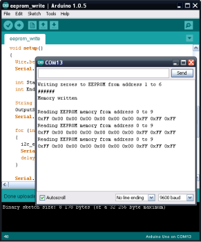
- Serial Monitor writing zeroes and reading values from test EEPROM.

Again, you can change the addresses which will be zeroed by editing the lines in setup() section.
void setup()
  {
...
    int StartAddr = 1;  // address to start write from
    int EndAddr = 6;    // address to end write at
...
Once you feel confident in reading and writing to the test EEPROM, you can proceed to the next part.