Since you disabled the internal Pull-up resistors on your Arduino board, the testbed is not working anymore. You need to add two resistors you obtained earlier to the testbed if you want to continue reading/writing to the test EEPROM.
These resistors should not be used when connecting to the TV’s I2C bus as the TV A-board logic already contains pull-up resistors. They are used solely for the purpose of reading the test EEPROM with the Arduino’s internal pull-up resistors disabled.
We will be driving the I2C bus with an external power source (still provided by the Arduino board, but from its 3.3V output, which is independent of the 5V output powering the EEPROM chip). Here is the altered wiring scheme:
-

- Arduino testbed schematics with external pull-up resistors
I only had some 10kΩ potentiometers at hand so I set them to ~4.7kΩ with a help of a multimeter and connected them according to the schematic. It does not matter what resistors you use as long as you fit within the required resistance.
-
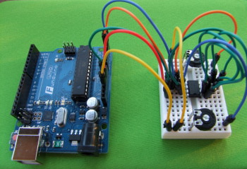
- My testbed using potentiometers instead of resistors

Once you have all the cabling connected, you should be able to read/write to the test EEPROM once again. Now we can proceed to the real deal. You can disconnect the whole testbed and prepare the cabling needed for connecting to the TV’s service port in the next section.
Next section: Restoring black level