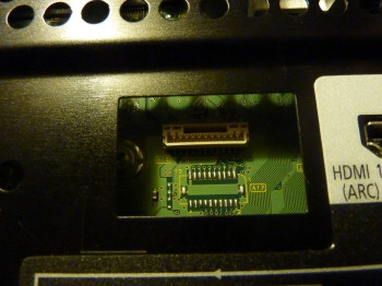
First, you should power off the TV with the manual switch on the front and disconnect the power to the unit. If you have the set wall-mounted, for the first time it will be probably better to remove it from the wall. After you have done this once and know the drill, you will be able to connect the service cable with the unit on the wall for future MLL resetting. The service connector on 11G and 12G models is easily accessible from the back without removing/unscrewing any back panels. You can locate it under the black plastic cover which can be opened with a flat screwdriver by bending the plastic notch. The service connector is a JST PH type, namely B11B-PH-SM4-TB. For 2010 models, the service connector is located under black plastic self-adhesive sticker (Panasonic cutting costs?) so you need to peel it off to gain access. The service connector is a JST GH type, model BM11B-GHS-TBT.
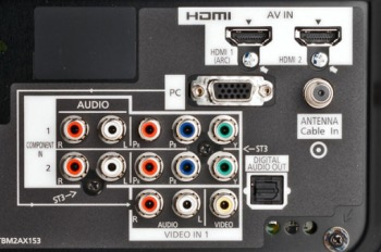
- TX-P42G10E: Service connector is located under the black plastic cover next to the HDMI2 input.
- TX-P42G10E: Plastic cover protecting the service connector.
- TX-P42G10E: Service connector located on the green PCB. The black plastic cover has already been removed.
- TX-P42G10E: B11B-PH-SM4-TB connector. PIN 1 is at the top.
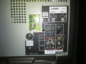
- TX-P46Z1E back view. Service connector is in the middle at the bottom just left of the stand mount.
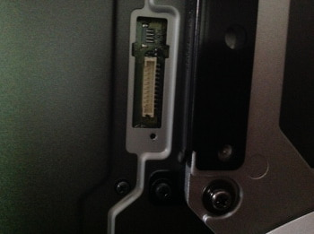
- Detail on TX-P46Z1E service connector. Pin 1 at the bottom.
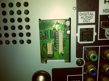
- TC-P50X1 back view. Black plastic cover already removed revealing green PCB.
- Detail on TC-P50X1 service connector. Pin 1 at the top.
- TC-P42G25: Panasonic used plastic sticker in 2010 models instead of re-attachable cover. Located top left.
- TC-P54VT25: Detail on the service connector located under the sticker. Pin 1 on the left.
- for the TX-P42G10E model (and possibly other G10 models as well), pin 1 is at the top, pin 11 at the bottom.
- for the TC-P54V10 model (and possibly other V10 models as well) the service connector is horizontal on the TV, with pin 1 towards the center of the TV.
- for the TX-P46Z1E model the service connector is vertical close to the stand on the left. Pin 1 at the bottom, pin 11 at the top.
The pin-out for the connector is as follows:
1 +5V
2 SRQ (Service Request)
3 GND (Ground)
4 GENX8_SCL (STBY EEPROM)
5 GENX8_SDA (STBY EEPROM)
6 PEAKS_SCL (PEAKS EEPROM)
7 PEAKS_SDA (PEAKS EEPROM)
8 PANEL_SCL (PANEL EEPROM)
9 PANEL_SDA (PANEL EEPROM)
10 I2C_CONT (I2C Control)
11 D_PCB_MODE (Process Control Block)
For accessing the A-board EEPROM through I2C bus, you will need to connect communication pins 9 and 8 to the Arduino’s pins A4 and A5. Also, you need to connect pins 3 and 10 to the Arduino’s GND pins, which will mute all other I2C masters on the bus so that the A-board EEPROM can talk to the Arduino board without disruption.
- Arduino connected to the JST service connector on Panasonic’s A-board.
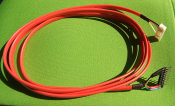
You could interconnect pins 3 and 10 right at the JST service connector and run only three wires from the back of the TV to the Arduino board, but such a cable could not be left connected to the TV after performing the reset, because the TV’s logic will force the panel to remain shut thinking you are still accessing the I2C bus. Therefore it is better to run four wires from the TV to the Arduino board and interconnecting those pins only at the Arduino by connecting to it’s both GND pins. This way you can leave the cable connected to the TV and tuck it behind once you’re done with the reset, keeping it ready for the future use.
- Service cable made out of 4-wire POTS cable.
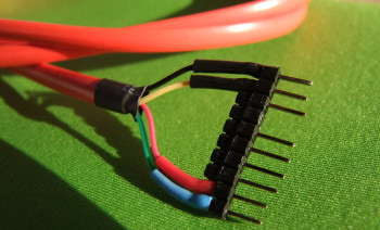
- Arduino header. I left the pins in between to make a stiffer contact with the board.
- Panasonic connector. Yellow cable is connected to PIN 3.
- Service connector with the cable attached.
- I fixed the service cable in place with a nylon cable tie.
Once you have the cable ready, you can proceed to the next page (or get a pre-made one while stock lasts).
Next: Reading A-board EEPROM





Could I use the 5v output on pin 1 of this port to produce a USB device charging cable direct from the TV? It would depend on what current output that 5v source is rated to I guess? Mark
Hi Mark, I have no idea.